Fluid Level Sensor Wiring Diagram
Fluid level control circuits, fluid level monitoring Level transmitter wiring diagram Fluid sensors sensorsmag magnetostrictive torsional dozen tanks
wiring picture | Level sensor, Water pump motor, Water pumps
Sensor level liquid coaxial cable sensors using intrinsically safe composition designed figure system implementation measuring Simple fluid level sensor circuit Circuit level sensor diagram cooling liquid seekic wiring
Level sensor water circuit liquid chip single conductive diagram 2008 basically november
Roon tony van fluid sensor level adaptation alarm waterIfm level sensor wiring diagram Fluid detector schematicLiquid level sensor circuit.
Pressure sensor diagram wiring air oil 20ma ato rs485 5v outputCircuit capacitive fluid Water alarmLevel transmitter liquid.

Wiring picture
Sensor probe liquidIfm level sensor wiring diagram Yd25 engine wiring diagramFluid level sensor wiring diagram.
Sensor level displacement position fluidSensor fluid schematic Liquid level sensor for water level, oil & mild-corrosive liquid levelLiquid level sensor circuit.

Liquid level sensors for industrial applications
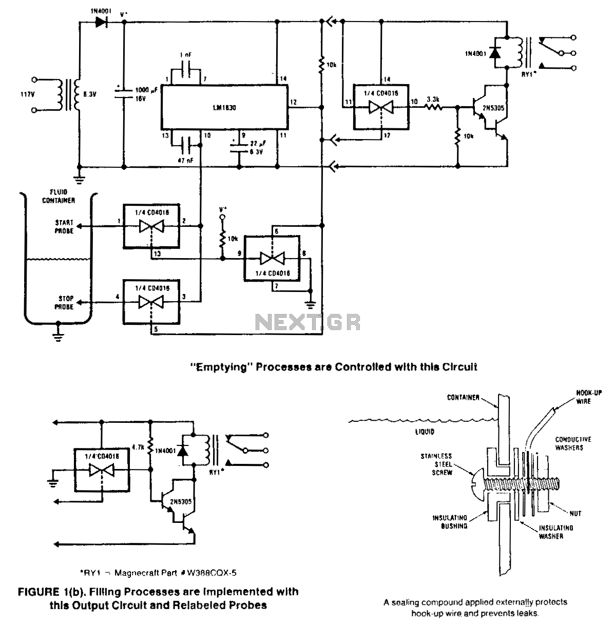
Level water sensor diagram wiring sensing liquidLiquid sensor circuit : sensors detectors circuits :: next.gr (a) the schematic diagram of the proposed liquid level sensor. (b) theIfm level sensor wiring diagram.
Water sensor circuit diagramIfm sensor coded conductors awg cables interface three Sensor level water arduino liquid use vc tab linksprite column text test titleWhat must todo: simple fluid level sensor.

Lm1830 single chip water level sensor circuit: basically a conductive
Pressure sensor for air/water/oil, 4-20ma/0-5v/rs485 outputSensors sensor infrared Position sensorIfm ure monitoring.
Liquid sensing: water level sensorBrake fluid level sensor wiring diagram Liquid level sensors for industrial applicationsUse liquid level sensor on arduino.

How do optical level sensors work?
2010 highlander washer fluid reservoir level sensor wiring diagramDiagram wiring fluid pump auxiliary washer 2010 mercedes water sensor benz reservoir highlander level car diagnostics temperature located where 센서 > fluid level control schematic diagramsWasher reservoir fluid level diagram 2010 sensor windshield highlander wiring location tank water hose addition problem low another fill.
Sensor level liquid circuit diagram water alarm electroschematicsA fluid sensor. 2010 highlander washer fluid reservoir level sensor wiring diagramLevel control fluid liquid circuit gr next sensor circuits.
For 1995-1998 ford mustang brake fluid level sensor connector
Level fluid control schematic sensors circuits detector2-channel fluid leak sensor – alec hewitt A dozen ways to measure fluid level and how they work.
.


Yd25 Engine Wiring Diagram - Wiring Diagram

Ifm Level Sensor Wiring Diagram

Liquid Level Sensor for Water Level, Oil & Mild-corrosive Liquid Level

Use Liquid Level Sensor on Arduino | LinkSprite Learning Center

How Do Optical Level Sensors Work? - SMD Fluid Controls

LIQUID SENSING: Water Level Sensor